FutureWrap Structural Leads the way in Structural Composite Repairs
By Professor Simon Frost
FutureWrap Structural repair systems are leading the way in structural composite repairs and proving to offer robust, and long term solutions for operators. The composite system provides both additional strength to steel structures, as well as acting as a seal to prevent any ingress of external fluids. Following its launch in 2019, it's thought to be one of the best repair systems on the market.
Here's how:
Overview
The Futurewrap Structural composite repair system is designed to be applied to damaged structural members, e.g. I-beams, structural members, roofs, panels etc. The damage is assumed to be caused by corrosion resulting in material loss rather than cracking and also that on application of the composite repair the corrosion process is halted. In general terms the repair is applied over the damaged area with the purpose of providing both additional strength to the underlying steel structure and also to act as a seal to prevent any ingress of external fluids, e.g. when applied to roofs or wall panels.
Materials
The FutureWrap Structural system consists of a carbon fibre reinforced epoxy resin composite material.
The carbon fibre is in the form of a woven non-crimped fabric. The reinforcement architecture comes in two forms, a uni-directional cloth and a quadraxial cloth. The uni-directional cloth has the carbon fibres aligned in a single direction and is 0.7 mm thick. The quadraxial cloth contains 4 layers of un-directional plies orientated with respect to each other 0/90/45/-45 degrees. The thickness of the quadraxial cloth is 1.25 mm.
The epoxy resin used comes is two forms. A low temperature ambient cure system which has a maximum operating temperature of 1000C and a high temperature system which requires post curing and has a maximum operating temperature of 2500C.
Applications
The intended applications in generic terms of the FutureWrap Structural system are:
- Roofs
- Floors
- Panels e.g. on accommodation modules
- I-beams
- Structural members, e.g. struts, CHS, supports
Defect types
The defect types to be repaired are limited to material or wall loss caused by corrosion. Crack or crack like defects are not considered.
Design approach
The design procedure for consists of two steps. These are:
1. Structural design (i.e. analytical design code solutions) to determine the required thickness of the repair.
2. Adhesive layer analysis to determine that the load can be transferred from the damaged steel component into the repair.
The output of the design calculation is the thickness of composite repair, the extent of composite repair beyond defect, and confirmation that the applied loads acting can be transferred into the composite repair.
The structural design involves calculating the thickness of repair from the supplied applied loads and moments. A simple analytical approach is adopted where the thickness of the repair is calculated using the maximum applied moment and loads, i.e. no account is taken of the moment or load profiles acting along the component. The in-plane load, moment and if relevant shear load calculations are performed separately with the maximum repair thickness resulting from any of the three calculations taken as the final repair thickness.
The adhesive layer analysis, based on a linear elastic fracture mechanics approach is used to assess whether or not the applied loads can be transferred into the composite repair, i.e. that is will remain bonded to the substrate. A typical profile of the adhesive layer stresses, peel and shear is presented in Figure 1.

What is apparent from this generic plot of the adhesive layer stresses, is that they are only present near the edge of the repair. In other words all the applied load transfer occurs within this region of the repair, not uniformly across the complete length of the repair.
Fire performance
To obtain a fire performance rating for a composite repair, e.g. A30, H60 a passive fire protection coating system, FutureWrap Fire will be required to be applied over the repair. A previous blog has discussed this repair product.
If no fire protection coating is applied over the repair then in a fire situation as the temperature increases above the glass transition temperature of the resin (for the LT system the glass transition temperature is 1400C and for the HT system is 2800C), the resin changes from a glassy to a rubbery state. In this rubbery state the modulus, strength of repair and adhesion strength are reduced. As the temperature increases further, the resin will eventually melt. For the LT resin system the melting temperature is approximately 2500C and for the HT system, 4500C.
Longevity and HSE perspective
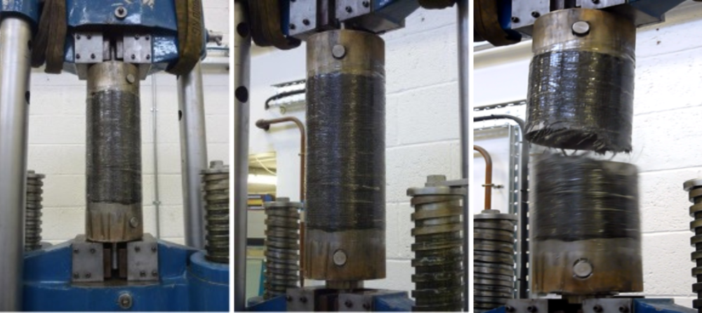
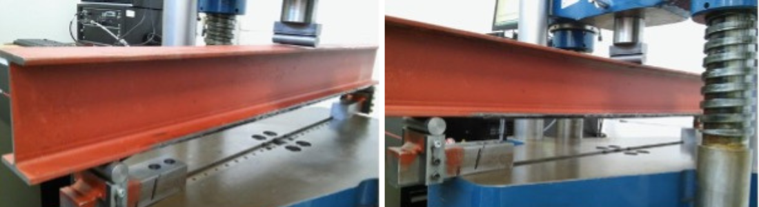
Examples of testing performed
The following pictures illustrate the testing performed on FutureWrap Structural. These tests were performed to provide demonstration of the appropriateness of the engineering design and installation of FutureWrap Structural repairs.